Support
Support provides you with the necessary files you may need to successfully install and/or plan for an installation of Danley products.
Sound is Everything & Danley Sound Labs
Danley Sound Labs is a renowned company specializing in the design and manufacture of high-quality, high-efficiency loudspeakers and subwoofers. Known for its innovation and superior audio performance, the company offers a wide range of products, including loudspeakers, subwoofers, amplifiers, and more.
Danley Sound Labs is headquartered in Gainesville, Georgia, United States.
Sound is Everything is located in Byron Bay, Australia.
Danley Sound Labs produces a wide range of professional audio equipment, including loudspeakers, subwoofers, amplifiers, monitors, and related accessories. Our products are engineered for superior sound reproduction across various applications such as live concerts, theaters, houses of worship, stadiums, and more.
You can purchase Danley Sound Labs products and related products through “Sound Is Everything” here in Australia. Contact us via this website.
Our patented Synergy Horn technology is a revolutionary loudspeaker design that combines multiple drivers on a single horn, achieving high efficiency, consistency, and reduced distortion. This results in an improved listening experience with superior coverage and audio clarity.
For technical support, please contact Sound is Everything via our website’s “Get in Touch” page. You can also refer to the product manuals and support documentation available on our website.
Sound is Everything complies to Australian Consumer Law, Danley Sound Labs and Sound is Everything offer comprehensive warranty on our products. The specific terms and duration of the warranty may vary depending on the product. For detailed information, please refer to the warranty section in our website.
Danley Sound Labs provides a range of products designed to meet a wide variety of audio needs. While we do not offer custom products per se, our experienced team is available to help you select and configure the products that best suit your specific audio requirements.
The Tapped Horn technology is a unique subwoofer design developed by Danley Sound Labs. It cleverly places the driver within the throat of the horn, allowing both direct radiation and horn-loaded output to combine. This innovative approach results in higher efficiency, or greater output using less amplifier power.
Danley Sound Labs products are used across various sectors that require high-quality sound systems. These include live events and concerts, theatres, houses of worship, educational institutions, sports stadiums, corporate settings, and more.
Yes we offer installation services and can install any Danley product for you Australia Wide,
Yes, we offer training to all of our customers who purchase products from us. We will customise a training and support package to your requirements.
You can find user manuals for our products on our website. Navigate to the “Support” section and select your specific product to access the associated user manual. Each product page also contains a link to the related user manual.
At Danley Sound Labs, quality assurance is a top priority. We conduct rigorous testing and quality checks at each stage of production to ensure that our products meet the highest standards of performance and reliability. Our commitment to excellence has helped us earn a reputation for delivering dependable, superior audio solutions.
You can stay updated about our latest products and updates by subscribing to our newsletter. You may also follow us on our official social media channels and regularly check our website for the latest news.
At Danley Sound Labs, we are committed to responsible business practices. We aim to reduce our environmental footprint by using sustainable materials where possible, optimizing our manufacturing processes to reduce waste, and adhering to regulations regarding waste management and recycling.
e don’t provide direct design and planning services, our technical support team is always ready to help. We can provide guidance on the best products for your needs and offer advice on system setup. For complex projects, we recommend working with a professional audio consultant or system integrator experienced with Danley Sound Labs products.
For speaker repairs, contact us directly. We can assist you with information related to repairs and parts required however some repairs may void warranty and will need to be done by Sound is Everything technicians directly.
If your amplifier is not working, you should first check the troubleshooting section in your user manual. If the problem persists, please contact Sound is Everything for further assistance.
The order processing time can vary depending on the product availability and shipping location. Sound is Everything will provide you with current build times and estimated shipping times.
Build times can very between 6-12 weeks.
Shipping (estimate only) for Danley products:
Air 20-30 Days
Sea 40-55 Days
If you’re experiencing issues setting up your new system, please refer to the product manual for initial troubleshooting. For further assistance, don’t hesitate to contact us. We can provide guidance and tips to help you set up your system correctly.
Loudspeaker/subwoofer setup
At Danley, we frequently receive questions about loudspeaker and subwoofer setups as well as other Danley product-related questions. Below you’ll find some of the most frequently asked questions about Danley products.
There are several factors that have to be considered/weighed when determining subwoofer placement Physical size is one of the obvious ones. Clearly the size and weight of the subwoofer is a consideration that will probably out weigh the sonic considerations. There are advantages and disadvantages to each one of the following situations. There is not a “best”, but rather a best for a particular situation-or best compromise. So the pros and cons of each will be discussed.
The four main variables are Ground or flown? Center cluster or split left/right. And of course variables/combinations of each. FLOWN OR GROUND PLACEMENT? Ground placement will usually result in more impact to the sound. This comes from a couple of factors.
Being physically closer to the subs can result in greater output for some listeners, and the coupling with the floor can give some tactile vibrations that can be felt. Flown subwoofers actually use the inverse square law to their advantage. Since the difference in level drop is the same from 1’ to 2’ as it is from 20’ to 40’, the level difference will be much more even. We encourage you to download DDT 2D and experiment to find the best solution for you. CENTER VS SPLIT clusters A center cluster will generally provide the most even response (without peaks and dips).
However it does so at the expense of being really loud in one area and quieter in all others. Split clusters (a sub on each side of the stage) will have some problems. Among those are a “power alley”, a louder area often right down the middle of the room. There will also be various peaks and dips in level throughout the room that will vary from place to place depending on the freq and the spacing of the subs. Again, you can use DDT to model all these configurations an evaluate what works best for you.
There are basically 2 different directional sub configurations: the cardioid array and the end-fire array. DDT 2 D is a great way to model both of these configurations.
There is a tutorial on cardioid sub arrays in the DDT 2 D manual. In BOTH cases, The price you pay for the directionality is more subs! With a cardioid array, some of the subs are facing forward, i.e. towards the audience, and some are facing towards the rear, or away from the audience.
The rear facing subs are used to provide cancelation thereby creating the familiar cardioid coverage pattern. The advantage to a cardioid array is more rear rejection. The major disadvantage is that the rear firing boxes do not contribute at all to the sound covering the audience. The end-fire system points all the subs towards the audience, but places them in a line, one behind the other like train cars. Spacing of the boxes is critical as it the application of delay to the boxes.
The advantage to an end-fire system is higher efficiency as al the boxes contribute to the audience sound. The disadvantages are that the array will likely require lots of room, and the spacing of the boxes is critical.
On most of the Danley products (the exceptions being the dual impedance models which will be discussed later), the NL4 jacks are wired to Pin 1 + and -. Pin 2 is passed through. A positive voltage connected to pin 1 + will cause the cone to move out of the basket. The two jacks are in parallel. So it does not matter which jack you use. Either jack is an input or a “pass through” or a jumper connection to another cabinet. DO NOT hook 2 channels of an amplifier (1 to each connector) to a single cabinet or damage to the amplifier will result.
DUAL IMPEDANCE SUBS On these cabinets the wiring is a little bit different. There is a locking switch that has to be pulled out and then moved to the other position and then let loose to lock into position. This is offered as a flexible option to those who want to power the subs in different way. In the 1×4 ohm position-the cabinet is wired up as single 4 ohm load to pin 1. Again, the connectors are in parallel. This will present a single 4 ohm load to the amplifier. However in the 2×8 ohm position, 1 set of drivers (or a single driver in most other cases) is hooked up to pin 1-again in parallel. Pin 2 is passed through to the other connector in either position. This will present 2- 8 ohm loads to the amplifier-so 2 channels can be used to drive the cabinet (or 2 amplifiers in bridge mono mode each) The second set of drivers (or other driver in most other cases) is hooked up to pin 2. In this case pin 2 is passed through to the other connector-making it in parallel. In the 2×8 ohm position, the loudspeakers (or sets of loudspeakers in the TH812) have no electrical connection to each other-so any number of different amp combinations could be used to drive the 2 independent loads. So it could be wired up with a single NL4 cable (1 amplifier on each set of terminals) or with 2 cables-one wired up to the pin 1 terminals and the other wired up to the pin 2 terminals-and plugged into the separate jacks.
In the Single channel operation, if you plug a signal into the pin 2 jack-nothing will happen (sound or electrically wise) as it is not connected to anything (except the other jack).
First you will need to get access to the rear of the high freq driver.
Different Danley products come apart different ways-so contact Danley for the particulars for the individual cabinets.
Unplug the wires going to the terminals on the diaphragm. This is usually a white and black pair of wires. The white wire (or lighter colored wire if not white) will go to the + or RED terminal.
There are usually 4 to 6 screws holding the diaphragm in place. Remove them and then carefully pull the diaphragm straight backwards. Please contact Danley Sound Labs to see if they want you to send the diaphragm or photos to them for evaluation of the failure. It is very important to make sure the gap where the voice coil goes is free of trash that may have been left over from the previous failure. The gap is the slot that is round. You should visually look into the gap with a flashlight to see if you see any small (they may be very small) pieces of anything, so you can check to see if you have removed them. You cannot see the complete open area-just the slot at the rear of the magnet.
Some debris can “hide” just under the rear plate. The two basic methods of debris removal both use masking tape.
One method is to fold a piece of tape at a 90° angle (with the sticky sides out), then fold one leg back over the other piece. This will form a triangle that is sticky on both sides. Stick the “pointy side” down as far in the gap as you can, and run it around the gap. Do this several times, each with a new piece of tape.
Another way is to use a business card with tape folded backwards over an edge-so the sticky side is out. Now push the card with the tape into the gap and run it around the gap. The card just gives you more “pushing power” to get the tape in further. Be sure to inspect the tape for any debris. Keep cleaning until it is all clean. Then visually inspect the gap to see if any small specs remain.
Sometimes a large “chunk” will be stuck to the side with the magnet pull greater than the stickiness of the tape. In that case insert a piece of tape into the gap (with the sticky side towards the debris) and then double over a business card and push it between the non sticky side of the tape and the magnet wall opposite of the debris. Then try to push the tape on to the debris to get better adhesion.
Sometimes you have to “fish out” some pieces. When the gap is clean, carefully push the new diaphragm into place.
NOTE: If there are any plastic spacers between the diaphragm and the magnet-BE SURE to REUSE them. They are specific to the magnet assembly-not to the diaphragm. Then screw down the mounting screws. They need to be good and snug, but not tight enough so as to deform the diaphragm. Hook up the wires to the terminals they were removed from and reassemble the cabinet.
While this may seem like a simple question, the real answer is quite complicated-with lots of variables and “it depends”.
For example. Are you asking how loud it will get-or loud will it measure on a SPL meter? These can be VERY VERY different. It depends on the response time of the meter-the weighting of the meter and so forth. At one very loud rock show we did we took some measurements. These are all with the same meter-at the same location-same band-same song. At FOH A weighted slow we were around 106-107dB. C weighted slow was around 118dB C weighted fast was around 128dB Peak/impulse was around 136dB That is a difference of 30, which is a ratio of 1000. Or to put it another way-the same difference as between a 1 watt amp and a 1000 watt amp. So you can see with the same loudspeaker-very different readings can be measured. We also have to assume your meter is properly calibrated for accuracy.
Cheap meters have been known to vary quite a bit. So while the loudspeaker system was producing 136dB-if you had a meter on A slow-you would only be reading around 106-107dB. And you might think that the loudspeaker system was not getting anywhere near as loud the specs show.
You also have to remember that music has a dynamic range-and the peaks are much higher (and shorter duration-hence the response time of the meter) than the average of the music. This has to be taken into account when figuring out which loudspeaker and amplifier size is needed for a particular job/loudness. So while the numbers published are what the loudspeaker can actually produce-what you read on your meter may be quite a bit lower-or not-depending on the settings and the quality of the meter.
DISTANCE When you move away from any loudspeaker (on axis) the sound pressure level will drop. How much depends on a number of factors. The following is assuming outdoors without reflections. Indoors-the room itself can have lots of influence on how much the sound drops off with distance. The reverb time of the room can also help to smooth out differences in level indoors-so the numbers ay not seem to “act right” in certain rooms. Outdoors the readings will be more consistent. Point Sources A point source loudspeaker will generally drop off at a rate of 6dB every time you double the distance. The difference between 1’ and 2’ is 6dB. The difference between 200’ and 400’ is 6dB. So you can see that the biggest differences are lost up close to the loudspeaker.
The formula is dB loss=20logxd1/d2. Lets’ say the SPL spec is 1m (standard) and you are at 30M distance from the loudspeaker. So 30/1=30. Take the log of 30 and you have 1.477. Multiply that by 20 and you have 29.5dB. So 30M away the SPL would be expected to drop 29.5dB. Or close enough to easily remember as 30M=30dB.
Another distance to easily remember is 10M=20dB. So if the max SPL is 130dB, then at 30M it will be around 100dB-accounting for the 30dB loss. This is also assuming ON AXIS measurements. If the point source is flown (typical) then the level at the rear of the listening area will remain pretty much unchanged-but the level up close will not be as loud as the 1M measurement would suggest. This is because the closest listener is not actually 1M away and they are in a lower level part of the coverage pattern-so very often the level is the same (or very close if well designed) for the closest listener and for the furthest listener (of interest). Line Arrays.
It is often stated that line arrays only drop off at a rate of 3dB whenever you double the distance from them. This is only partially true. It is true as long as the line is long enough in relation to the particular freq that this will happen. For the high freq this does happen (with lots of interference along the way). But with low freq-unless the line is very large-it will drop off at a rate of 6dB-just like a point source.
So with those types of devices, you have to be specific about the freq of interest when stating loss over distance.
Whether or not a particular sub is suitable for a particular application has nothing to do with the number of people in attendance and little to do with what full range box is being combined with it.
What is important is what freq range is needed (some musical styles require a lot lower response than others) and how loud it needs to be. And loud means very different things to different people. It needs to be expressed in real numbers (Sound Pressure Level). If using the terms “keeping up” with a particular full range box, that also has very different meanings. If they mean the output of the sub and full range box have equal SPL capabilities, then they are probably going to be disappointed. In most cases the subs need to “outrun” the tops by quite a bit. 6-10dB is a good starting number, with some styles needing as much as 16-20dB more capability to make it “sound right”.
Let’s say that your full range cabinets are capable (and you are planning on running them this loud) of 130dB SPL. Then you should be looking at a sub system that is capable of something in the range of 140-150dB-give or take. Our ears generally like more bass than we do full range. So you have to think in terms of SPL (Sound Pressure Level) when trying to determine if a particular sub is loud enough. We assume you have already chosen models that go low enough for a particular music style. That is another topic altogether. It is not so much the number of people (100 people could take up a large or a small space-depending on how tightly packed they are), but the area of the space. And this also includes the height.
The particular construction of the walls can also greatly affect how much bass is in a room. The wall construction can actually absorb particular frequencies and “suck” them out of a room. As a general rule, use the inverse square law for determining how much “subbage” you need. That simple states that as you move twice as far from a certain point, the level will drop 6dB. Inside a room the actual drop may be less (due to room gain at certain freq), but just consider that to be “free sound”.
Typically outside you need at least twice as many subs as indoors-for a given area. For example: let’s say you have a sub that has a continuous output capability of 130dB. The program and peak ratings should be used as just that-overhead-but not depending on the those numbers to give a constant output level. Be very wary of using peak output ratings as they can often be misleading to what the actual/achievable SPL is. Let’s say that a particular listening position that you are interested in is 11 meters (36 feet) away from the loudspeaker.
Since the spec distance is 1 meter, this leaves a distance of 10 meters that you need to figure out the loss. The formula is 20 log D1/D2 . Since the distance is 10 meters away from 1 meter. D1/D2=10. Take the log of that (1) and multiply by 20 and you have your loss due to distance which is equal to 20dB. OR you could use the “seat of the pants” method. Do the easy math. Going from 1 meter to 2 meters is 6dB. From 2 meters to 4 meters you lose another 6dB. From 4 to 8 meters another 6dB. So going from 1 to 8 meters you have lost 6+6+6dB or 18dB. Now 8 meters is still a little bit short of the target 10Meters so you add an extra 2dB or so and you get the same thing as the formula-or 20dB.
Of course further away would be an even lower level. You can also work backwards to figure out how much sub level you will need. Let’s use the above example and say you need 115dB at a particular listening position. Since that distance (10 Meters) has a loss of 20dB, you ADD 20 to the 115 dB needed level and you end up with 135dB. So your sub(s) needs to be capable of producing 135dB continuous. MULTIPLE SUBS As a general rule when you double the number of subs AND double the amplifier power available to them, you will get a 6dB increase in SPL. This number can vary a good bit, but will never be greater than 6dB-and could be as little as 3dB. So going from 1 to 2 subs will gain you 6dB. So if the subs have a 130dB rating, then 2 subs would be 136dB. 2 to 4 subs (and amplifiers) would get you to 142dB. But if you need to get to 148dB, then you will need 8 subs (and amplifiers).
As you can see it takes increasingly larger amounts of gear to get the same change in SPL. MUSICAL STYLES Another thing to consider when choosing any loudspeaker is the musical style that will be used. Or more precisely- the dynamic range of the musical style. Dynamic range is NOT how loud it is, but rather the ratio of the loudest sounds to the softest. Some styles have a very large dynamic range (classical), while others have a very limited dynamic range (dance music-grunge rock etc), Signals with a limited dynamic range are going to be abusive to loudspeakers in the form of heating. This is because the loudspeaker does not have a chance to “cool off” in between loud peaks in the signal. So if you are choosing loudspeakers for use with a limited dynamic range signal, you may want to “downgrade” the SPL in the calculations so you don’t run the risk damaging the loudspeakers. This will force you to use more loudspeakers-but at least they won’t tear up due to heat. The wattage ratings are based on “normal” program content-not heavily compressed music styles. So the wattage ratings for those styles would be less (and therefore less SPL capability) than with “normal” music.
CONCLUSION As you can see, it is not an easy “How many subs do I need for 400 people” type of thing. You have to take into account the actual physical distances involved-the musical styles, the freq response and so forth. But a little simple math can go a long way towards figuring out how much “subbage” you actually need.
“AT” (Aqua Tight) – Full fiberglass finish for maximum moisture resistance. Includes (2) fiberglass layers, inside and outside the cabinet, a special polyurea coat bonded to the fiberglass exterior & (2) topcoat layers of UV resistant color stabilizer. This also includes powder coated stainless steel grilles, an acoustically transparent moisture barrier is attached to the grill, sealed waterproof cable leads (12’ length standard) and full caulking of all external joints (except for the “weep” opening at the bottom of the grill). Driver cones are weatherproofed and, a weatherizing sealant is applied to the input plate, handles, and other cabinet fixtures.
There are no limiter settings that can guarantee that you will not “blow up” a loudspeaker-unless it is set so low as to inhibit the capability of the loudspeaker to get loud.
There is a large “grey area” for the settings. The actual settings for protection will depend on the a few things, the dynamic range of the material being played-the type of material and so forth. Some musical styles are more abusive on loudspeakers than others.
Below is a basic guideline. I prefer to actually use 2 limiters if possible; one as a “peak stop” and the other as a “heating” limiter. The 2 things that cause damage to loudspeakers are over excursion (too much cone movement which causes physical damage) and overheating-which can melt wires, glue etc. I prefer to talk in terms of voltage applied to the loudspeaker-because that is easy to measure. The following formula should be used when converting power (wattage) to voltage. Take the square root of (The power rating X rated impedance). This will give a voltage to be measured. This voltage should be measured at the output of the amplifier using a sine wave WITHOUT a loudspeaker hooked up. If the loudspeaker is hooked up-it will probably be destroyed.
For the peak stop limiter-the shortest attack time should be used and the voltage would be equal to the program rating of the loudspeaker. A ratio of 20:1 should be used. For example, the voltage applied to a 4 ohm ( nominal) loudspeaker rated at 2000 watts program, would be the square root of (2000×4) or 126 volts. But if you push the level to where this limiter is limiting hard (lots of reduction) then your average level will be a lot higher and could cause heating damage because the average level applied will be higher. The peak stop is just to stop the occasional peak-not a long term “leveler”.
The heating limiter is a different story. The actual setting could vary a good bit-depending on the parameters available and the type of source material being played etc. A typical range would be from around ½ the continuous rating up to the continuous rating. Attack times should be at a minimum 100ms and preferably around 2-3 seconds.
As a general rule, longer attack times would result in lower voltage settings. The ratio should be at least 6:1 and up to 10:1 or higher. The voltage is calculated from the continuous rating (not the program as for the peak limiter), and ½ the rating is a good start. So for the same loudspeaker as above the continuous rating of 2000 watts program is 1000 watts. So half of that would be 500 watts. So the square root of 500×4 is 45 volts. The only time this limiter would be engaged is when the 45 volt settings is exceeded for more than the attack time (2-3 seconds).
The maximum setting would be equal to the continuous rating, or square root of 1000×4 or 63 volts. So somewhere between 45 and 63 volts would be a good setting for the slow or “heating” limiter. You may be able to set these higher and be just fine-especially with material that has a large dynamic range-NOT with compressed MP3s or dance music that is mixed to be as loud as possible, because the dynamic range is not very large on those sources.
The best way to measure the voltage is to use a sine wave (at the correct freq range being used) going into the compressor/DSP etc and turn the threshold all the way up, or to as high a value as possible. Then using a volt meter hooked to the output, adjust the level (of the generator or the compressor input –NOT the compressor output or amplifier level control) until the voltmeter measures the correct value. Then turn down the threshold level until the limit meter just starts to register. This is usually 1dB. You should also notice that the voltage has gone down just a little bit. This would be the correct setting. DO NOT change the amplifier gain or compressor output levels-as this will throw off the actual threshold set.
The big problem is that our cabinets are not heavy enough. And if we made them heavier, people would complain about the weight. ☺ There is a lot of sound pressure that moves back and forth, and that is what is causing the movement. Rubber mats are a good idea. Another idea is strap them together through the handles and wheels. Stacking them up and laying them on their sides is also another idea to help keep them from walking around.
The Tapped Horn is not like a normal folded horn. The effective path length is not the path length of the horn. It is somewhere between the direct path from the drivers to the exit (on one side of the driver(s)) and the path all the way through the horn on the other side of the driver(s). The path length varies with frequency. How you integrate it into your system depends also on the phase response of the full range loudspeakers used-type of crossover filters and slopes used. Depending on the crossover freq and delay used, sometimes it is best to flip the polarity of the tapped horn in order to get the best response. This will need to be either measured or tested to be sure what is best.
Here is a simple test to get close. Choose whatever crossover freq you want and put that frequency – ( use a sine wave) into the system-driving both the Tapped horn and the full range loudspeaker. Increase the delay time on the full range loudspeaker until you get a null and adjust so you get the maximum null. If you don’t get a null-but rather something that sounds like a bump, try reversing the polarity and adjust again. When you have the delay time in the deepest part of the null-invert the polarity on the sub and you will be done. The lower freq the Tapped horn goes, the longer the delay time will generally be. But in the range of 3-20ms would be typical-but it could be longer or shorter depending on the particular setup.
Athletic Design Guide
Software Support
Whether you’re an active user of the EASE® software suite or simply need access to DNA Software Engineer, you’ve come to the right place. If there’s something that you can’t find, feel free to contact us and we’ll be glad to check on availability.
Danley provides CLF files for a variety of Danley loudspeakers and subwoofers.
Simply click on the file below to download:
Click to Download the CLF Viewer
CLF Files
DNA System Engineer DSP Control and Monitor
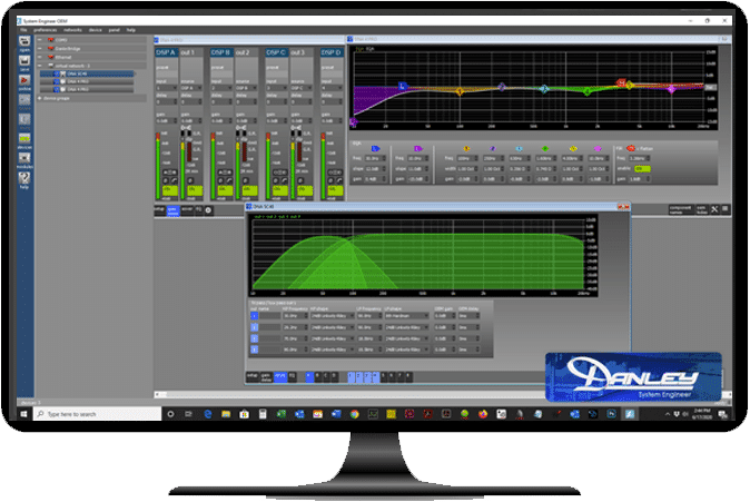
System Engineer is a highly unified control and monitoring PC application. It is a solidly engineered platform developed for the Danley Sound Labs DNA series amplifiers and processors. One click and you are online to a whole network of DNA devices. A double-click and you can control any of the devices. Plug another DNA device into the network and, thanks to Continuous Discovery, see it being automatically added to System Engineer.
Drag an EQ curve with your mouse to control the EQ in real time. Adjust a control on the front panel of the device and watch the System Engineer panel change smoothly in sympathy. Drag devices to a Group and you have group control of any number of devices. You can even design a system in your hotel room by adding an offline control panel, editing the control parameters and saving the resulting file. The file can then be loaded into a device when you get to the venue.
Simple but Feature Rich
We have worked hard to make System Engineer as simple and intuitive as possible. This apparent simplicity belies a sophisticated, comprehensive workhorse built on a solid core technology designed our software engineers. System Engineer will allow you to connect a number of devices and use it to set up, control, and monitor them. System Engineer may be used for programming factory settings or configuring installations as well as live control and monitoring of devices during a performance. System Engineer can control and monitor several networks consisting of many devices simultaneously via Ethernet (or BvNET or USB for some product types).
System Engineer
- One click finds devices across all your network
- OEM Parameter locking/hiding features
- Integration with EASERA SysTune
- No manual device addressing needed
- Continuous Discovery finds new devices
- Controls can be adjusted on the device too
- Powerful Grouping with overlays for EQ, Gain and Delay
- Fast metering
- Panel positions retained between sessions
- Drag-able curves
- Copy/paste EQ curves between channels or devices
- EQ Palette
- Mute All (system mute)
- Temperature, protection and status logging
- OEM Parameter locking/hiding features
- Integration with EASERA SysTune
DSP Software
The latest for you DSLP 48 processor.
EASE Files
Making your modeling easier.
The EASE® software suite provides system designers and consultants with an invaluable set of tools for all aspects of professional practice, from detailed, realistic modeling and simulation of venue acoustics and sound system performance to informative and engaging client presentations, as well as professional data assessment and verification.
User Manuals
To simplify access to user manuals, user manuals may also be found on each individual product page. Simply click on the link below to download the respective user manual.
Warranty Info
Sound is Everything complies to Australian Consumer Law.
Danley Sound Labs product warranty is covered in the specific user manual.
Sound is Everything offers the following warranty on Danley products, which covers product purchased directly from us in Australia. The warranty covers product which has been installed and operated under normally accepted standards. The warranty on standard-finish, non-weatherised products is five years against defects in materials and workmanship. The warranty on products in the OS line carry a five-year warranty against defects in materials and workmanship. Aqua Tight finish (AT) products carry a three-year warranty against defects in materials and workmanship. Aqua Resistant finish (AR) products carry a three-year warranty against defects in materials and workmanship. The installation of non-weatherised product in an outdoor area exposed to the elements and/or a corrosive environment will result in a voided warranty. In order for the warranty to be valid, all outdoor installations and/or installations exposed to the elements or a corrosive environment must be either the AT finish or “OS” series product.
The standard AT exterior colour is “Granite Peak Gray” (Sherwin Williams colour code SW6250) and must be used for a full AT warranty. In specific case-by-case situations, a custom colour can be used when agreed upon in writing between Danley and the Danley dealer/end-user. The use of a custom colour on AT products may affect the length of the warranty.
The warranty period starts on the date of purchase from Sound is Everything to an authorised Australian Danley dealer. In a case where a Danley dealer sells new product from their existing stock, dated proof of purchase by the end-user (i.e. receipt) will be required.
Coverage: Danley will repair or replace the product and/or defective portion of the product if it becomes defective under normal use and service during the term of this warranty. Sound is Everything is not responsible for any labor costs, fees, shipping or any other costs associated with the repair of a Danley product incurred by the user.
Repairs may be performed using new or refurbished parts that meet or exceed Danley specifications for new parts. If Danley US elects to replace the product, the replacement may be a reconditioned unit. The buyer will be responsible for any removal or re-installation charges and for any shipping charges if the product must be shipped for warranty service. However, Sound is Everything may pay the Australian portion of return shipping charges provided the product is still under warranty and the “ship to” destination is in Australia.
This warranty does not cover damage, deterioration (due to a corrosive environment) or malfunction resulting from accident, negligence, misuse, abuse, improper installation or operation, repair or attempted repair by someone other than an authorised Danley or Sound is Everything service tech.
This warranty does not cover any product with an altered serial number, damage due to power line surge or related electrical abnormalities, improper grounding, lightning damage and/or acts of God, damage during shipment (claims must be presented to the carrier), theft and/or vandalism, damage due to the use of non-weatherised (stainless steel or aluminium) or unsealed hardware, and defects resulting from normal wear and tear. This warranty is “non-transferable” and only covers the original purchaser. To obtain Warranty Service: please contact your authorised Sound ism Everything dealer or sound contractor for instructions on warranty claims, or contact Sound is Everything directly on 0403229317. You may also email us at sales@soundiseverything.com.au and/or the dealer’s Customer Service Representative. A product requiring shipping should be packed securely either in original packaging or in packaging of similar quality. The shipping method should be the same as was used when the product was received to help ensure damage doesn’t occur during shipping. Any damages that occurred during shipping or due to improper packaging will not be covered under warranty. No products shipped will be accepted unless prepaid or prior agreement with Danley has been arranged. All returns must be accompanied by a Return Authorisation Number (RMA). If any returned product is found ineligible, the cost of repairs will be forwarded to the owner, the product will be repaired, and returned to the buyer once payment for repair costs and shipping is received.
The warranty for the DNA amplifiers covers against manufacturers defect for three years from the shipped date.
The following is not covered by warranty:
If the amplifier is mounted in a mobile rack it is important that the rear is supported with a rear rack mounting kit. Damage caused by insufficient support is not covered by the warranty. The rack kits are not included and must be ordered separately.
It is the responsibility of the user to ensure that dirt, liquids, and vapour from theatrical smoke and fog machines does not enter the amplifier. Damage so caused is not covered by the manufacturer’s warranty.
The device must be grounded to suitable power; failure to do so may affect performance and/or operation and will invalidate the warranty and could be potentially hazardous.
If there is an issue with the amplifier, please contact our office on 0403229317 or email your Sound ism Everything customer service agent and/or representative. All warranty situations will be assigned an RMA# and will need to be packaged like it arrived and returned to Sound is Everything or depending on the issue, Danley Sound Labs, Inc. US for repair. Sound is Everything is not responsible for damages that occur during shipping and all charges and fees to ship the product for repair may be the customer’s responsibility, we highly recommend insuring your shipment. The timeframe to resolve issues may vary on a case by case basis and can take an extended amount of time. Sound is Everything does reserve the right to send refurbished or repaired units as replacements.
Danley Sound Labs, Inc. reserves the right to change the design of any product from time too time without notice and without obligation to make or provide for corresponding changes in products previously sold or manufactured.
This warranty is in effect for all Danley products sold after November 2, 2017, and supersedes all other warranty statements previously published.
Digital Tools
Direct Sound System Modeling Software
Danley’s Direct Sound System Modeling Software is a powerful tool to help sound engineers and system designers create room models and to determine the best Danley products for any room.